Ultrasonic flowmeter PRAMER-510
Type: time-and-frequency ultrasonic flow meter, operation is based on transit-time differential method.
Advantages: No construction elements inside the flow passage, high measurement stability, noise immunity, possibility of application at low conductive fluids.
PRAMER-510 allows to measure consumption of liquids in both directions of the flow in pipelines with diameter up to 2000 mm.
Application: ultrasonic flowmeters are used at pressure pipelines for measurement of liquids flow (water, industrial oil, waste water, stratal water, etc.) in various fields of industry and municipal engineering.
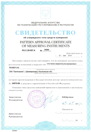
Ultrasonic flow meters Pramer-510 are registered in State Register of Measuring Instruments, № 24870-09.
Construction: PRAMER-510 consists of 1 or 2 measuring sections with flanges and piezoceramic transducers, electronic signal converter and connection cable up to 150 meters (or more upon request).
DN, mm: 40; 50; 65; 80; 100; 125; 150; 200; 250; 300 - in serial production,
DN, mm: from 300 to 2000 – upon request.
Flow meters with DN 300 mm and more can be mounted with direct in-cut of ultrasonic sensors.
Table 1: Modifications of flow meters depending on quantity of measuring sections and constructive features.
| Version of flow meter | DN, mm | Qty of measuring sections | Qty of acoustic channels at measuring section | Disposition of transducers at measuring section |
|---|---|---|---|---|
| 01 | 40-2000 | 1 | 1 | diametrical |
| 02 | 40-2000 | 2 | 1 | diametrical |
| 03 | 100-2000 | 1 | 2 | chordwise |
Controlled medium parameters:
Temperature range: from -20 (without freezing) to +150 C;
Gage pressure: max 1.6 MPa or 2.5 MPa;
Kinematic viscosity: not more than 5* 10-6;
Volume content of gas and solid inclusions: not more than 2%.
Operation conditions:
Ambient temperature:
for measuring sections: from -30 to +55 °C;
for electronic signal converter: from +10 to +55°C;
Relative humidity: up to 95% (at temperature max +30 C, without condensation);
Atmospheric pressure: 84,0...106,7 kPa.
Table 2: Maximal (Qmax), transit (Qt) and minimal (Qmin) values of measured flow depending on DN and calibration method.
| Flow rate, m3/h (at hydraulic method of calibration) | DN, mm | |||||||
|---|---|---|---|---|---|---|---|---|
| 40 | 50 | 65 | 80 | 100 | 125 | 150 | 200 | |
| Qmax | 50 | 70 | 125 | 200 | 300 | 450 | 630 | 800 |
| Qmin | 0.5 | 0.7 | 1.25 | 2.0 | 3.0 | 4.5 | 6.5 | 12 |
|
Notes: 1) Velocity of flow at Q max does not exceed 11 m/sec. 2) Qmax, Qt and Q min for DN 100 mm and more at indirect method of calibration can be calculated as follows: Q max = 0,03Dn2, Qt = Q max/50, Q min = Q max/100. |
||||||||
Accuracy
| Flow meters version 01, 02 | Flow meters version 03 | ||
| hydraulic method of calibration | indirect method of calibration | hydraulic method of calibration | indirect method of calibration |
| from Qmin to Qmax: ±1,5% | from Qmin to Qр: ± 2,0%; from Qр to Qmax: ± 1,5% |
from Qmin to Qmax: ±1,0% |
from Qmin to Qр: ± 1,5%; from Qр to Qmax: ± 1,0% |
Technical characteristics:
Protection degree: IP55 - for electronic transducer; IP67 - for measuring sections.
Power supply: 187-242 V, (50± 1) Hz.
Power consumption: not more than 10 W.
Frame sizes of electronic transducer (max): 222x170x56 mm.
Average life time: not less than 12 years.
Recalibration interval - 4 years.
Warranty period - 4 years.


